We use cookies to make your experience better. To comply with the new e-Privacy directive, we need to ask for your consent to set the cookies. Learn more.
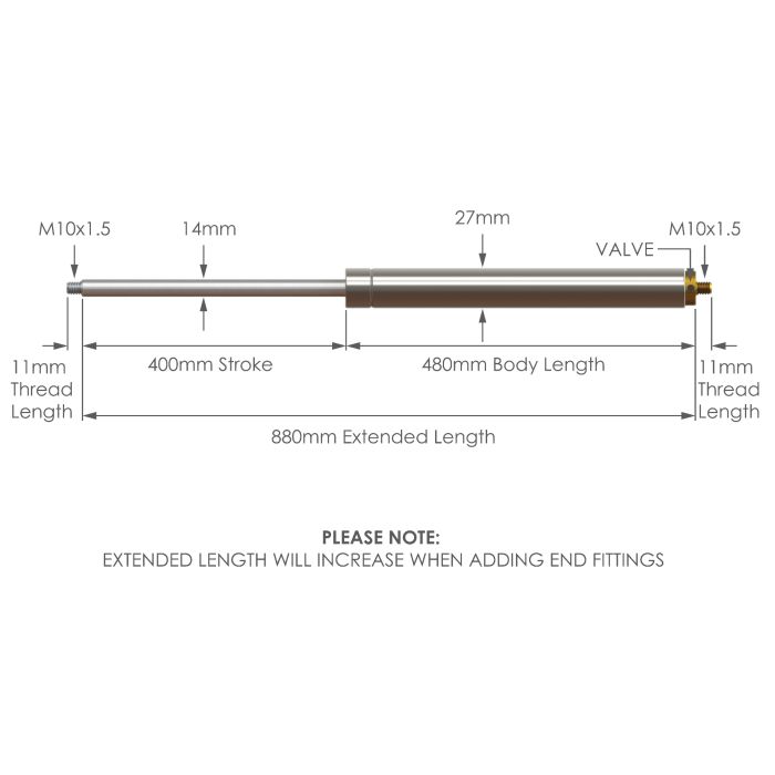
NS-SS-V-14-400 Stainless Steel 316 Variable Force Gas Strut
SKU
NS-SS-V-14-400
| Strut Force Type | Adjustable Force |
|---|---|
| Stroke | 400mm |
| Extended Length | 880mm |
| Rod Diameter | 14mm |
| Body Diameter | 27mm |
| Force Range | 150 - 2500N |
| Force Progression | 52% |

£117.37
All prices exclude VAT
VOLUME DISCOUNTS
- QUANTITYPRICE
- 6 + £111.49
- 20 + £93.90
- 50 + £82.15
-
Product codeProduct DescriptionStock Status
-
NS-SS-V-14-400NS-SS-V-14-400 Stainless Steel 316 Variable Force Gas Strut
-
SSB15Stainless Steel 316 Ball Joint End Fitting with 10mm Thread
-
SSE13Stainless Steel 316 Eye End Fitting with 10mm Thread SSE13
-
SSC3Stainless Steel 316 Clevis Fork with 10mm Thread
-
SSBRK-8SSBRK-8 Stainless Steel 304 8mm U Shaped Bracket with 50mm Fixing Centres
-
SSBRK-8-90SSBRK-8-90 Stainless Steel 316 8mm U Shaped Bracket with 51mm Fixing Centres
-
DC-SD04-BLK14mm Rod Dust Cover for 27mm Body Gas Struts